
Introduction
Approximate method for structural analysis is frequently used among civil engineers. This method is most effective while designing a building. This method is also useful for analysing other structure. But in this blog we will talk about analysis building frame with approximate method and at the end we will discuss how this can be done using python language. Python code will be provided. This script can also be used for analysing other building frame by changing loads and dimensions.
Approximate method
First we will talk about approximate method. In this post we will discuss about the part of the approximate which is used solving building frame. The most popular one is the portal method which is used for lateral loads. The other technique is solving for gravity loads.
Portal method for lateral loads
The portal method for analysing fixed-supported building frames requires some assumptions discussed below.
- Since it is assumed that the point of inflection is the place of zero moment and it is found at the centre of each member. That is why a hinge is placed at the centre of each beam and column member.
- Shear at the interior column hinges is assumed twice that at the exterior column hinges, as the frame is considered to be a superposition of portals.
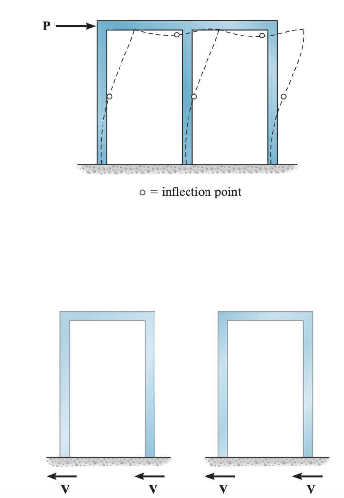
These assumptions make the structure statically determinate yet stable under loading.
Python code for solving building frame by portal method
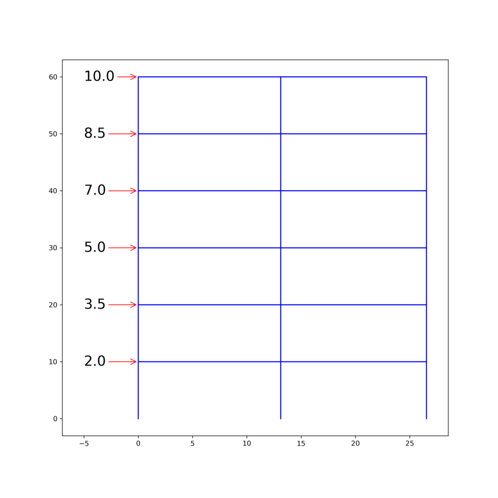
The provided python code can be used for solving portal frame under lateral loading. Dimensions, load, storey and number of bay can be changed in the script. Note that, force unit is in kilo-pound and length is in feet.
Script
import numpy as np
import matplotlib.patches as patches
import matplotlib.pyplot as plt

height = 10 # Floor height
storey = 6
bay = 2
bay_widths = np.array([13.125, 13.42])
#force_list = np.array([10, 8.5, 7, 5, 3.5, 2])
force_list = np.array([2, 3.5, 5, 7, 8.5, 10])

bay_widths_cm = np.hstack((0,bay_widths.cumsum()))
heights = height*np.ones(storey)
heights_cm = np.hstack((0,heights.cumsum()))

h_line = storey*bay
v_line = (bay+1)*storey

def frame():
    fig= plt.figure(figsize=(10,10))
    ax = fig.add_subplot(1,1,1)

    for i in range(storey):
        for j in range(bay):
            ax.plot([bay_widths_cm[j],bay_widths_cm[j+1]],[heights_cm[i+1], heights_cm[i+1]], color='blue') #Horizontal line

    for i in range(storey):
        for j in range(bay+1):
            ax.plot([bay_widths_cm[j], bay_widths_cm[j]], [heights_cm[i], heights_cm[i+1]], color='blue')
    return fig, ax


fig, ax = frame()
for i in range(storey):
    arl = 5
    ax.annotate(str(force_list[i]), xytext=[-arl, heights_cm[i+1]-0.7],
                 xy=[0, heights_cm[i+1]],
                 arrowprops=dict(arrowstyle="->", color='red'),
                fontsize=12, size=20)
ax.set_xlim(-bay_widths[0]*0.3, np.max(bay_widths_cm) + bay_widths[0]*0.3)
fig.savefig('Frame_with_lateral_load.png', dpi=300)

shear_unit = force_list[::-1].cumsum()/(bay*2)
csf = np.zeros((storey, bay+1))
csf_shape=np.shape(csf) #shear force for column
cmt = np.zeros((storey, bay+1))#Bending moment for column
bmt = np.zeros((storey, bay))#Bending moment for beam
for i in range(storey):
    csf[i]=shear_unit[i]*2
    csf[i, 0] = shear_unit[i]
    csf[i, -1] = shear_unit[i]

## Shear force diagram for column
fig_f, ax_f = frame()
for i in range(storey):
    for j in range(bay+1):
        ax_f.text(bay_widths_cm[j], heights_cm[i]+(height/2) , csf[::-1][i,j])
        rect = patches.Rectangle((bay_widths_cm[j],heights_cm[i]),
                                 csf[::-1][i,j]*0.4,height,linewidth=1,edgecolor='r',facecolor='green', alpha=0.5)
        ax_f.add_patch(rect)
        #ax_f.text(bay_widths_cm[j]-2, heights_cm[i]+1 , csf[::-1][i,j]*height*0.5)
        #ax_f.text(bay_widths_cm[j]-2, heights_cm[i]+height-1.5 , csf[::-1][i,j]*height*0.5)
ax_f.set_xlim(-bay_widths[0]*0.3, np.max(bay_widths_cm) + bay_widths[0]*0.3)
fig_f.savefig('Shear_force_column.png', dpi=300)


## Bending moment diagram for column

fig_g, ax_g = frame()
for i in range(storey):
    for j in range(bay+1):
        mnt = csf[::-1][i,j] * height/2
        cmt[i,j]=mnt
        ax_g.text(bay_widths_cm[j], heights_cm[i]+(height/2) , mnt)
        #rect = patches.Rectangle((bay_widths_cm[j],heights_cm[i]),
        #                         csf[::-1][i,j]*0.4,height,linewidth=1,edgecolor='r',facecolor='none')
        ax_g.plot([bay_widths_cm[j], bay_widths_cm[j]+(mnt*0.05),  bay_widths_cm[j]-(mnt*0.05), bay_widths_cm[j]],
                  [heights_cm[i], heights_cm[i], heights_cm[i]+height, heights_cm[i]+height],
                          color='red')
        #ax_f.add_patch(rect)

ax_g.set_xlim(-bay_widths[0]*0.3, np.max(bay_widths_cm) + bay_widths[0]*0.3)
fig_g.savefig('Moment_diagram_column.png', dpi=300)

## Bending moment diagram for Beam

fig_h, ax_h = frame()
for i in range(storey):
    for j in range(bay):
        bmb = (cmt[i,0]+cmt[i+1,0]) if i+1<=storey-1 else cmt[i,0]
        bmt[i,j]=bmb
        ax_h.text((bay_widths_cm[j]+bay_widths_cm[j+1])/2, heights_cm[i+1] , bmb)
        ax_h.plot([bay_widths_cm[j], bay_widths_cm[j], bay_widths_cm[j+1], bay_widths_cm[j+1]],
                  [heights_cm[i+1], heights_cm[i+1]+(bmb*0.04), heights_cm[i+1]-(bmb*0.04), heights_cm[i+1]], color='red')
        #print ('Storey:',i,'Bay:',j,'Column_shear:',bmb)
        #ax_g.text(bay_widths_cm[j], heights_cm[i]+(height/2) , mnt)


ax_h.set_xlim(-bay_widths[0]*0.3, np.max(bay_widths_cm) + bay_widths[0]*0.3)
fig_h.savefig('Moment_diagram_beam.png', dpi=300)

## Shear force diagram beam

fig_i, ax_i = frame()
for i in range(storey):
    for j in range(bay):
        sf = np.round(bmt[i,j]/(bay_widths[j]*0.5),2) #Shear force
        ax_i.text((bay_widths_cm[j]+bay_widths_cm[j+1])/2, heights_cm[i+1] , sf)
        #ax_i.plot([bay_widths_cm[j], bay_widths_cm[j], bay_widths_cm[j+1], bay_widths_cm[j+1]],
        #          [heights_cm[i+1], heights_cm[i+1]+(sf*0.4), heights_cm[i+1]+(sf*0.4), heights_cm[i+1]], color='red')


        rect = patches.Rectangle((bay_widths_cm[j],heights_cm[i+1]),
                         bay_widths[j],sf*0.4,linewidth=1,edgecolor='r',facecolor='green', alpha=0.5)
        ax_i.add_patch(rect)

ax_i.set_xlim(-bay_widths[0]*0.3, np.max(bay_widths_cm) + bay_widths[0]*0.3)
fig_i.savefig('Shear_diagram_beam.png', dpi=300)
Approximate method for distributed gravity loads
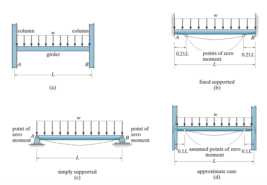
The assumptions to make a building frame statically determinate for distributed gravity load are as follows.
- Zero moment is assumed to be found at 0.1L from the left support for a beam.
- Zero moment is assumed to be found at 0.1L from the right support for a beam.
- The axial force in a beam is assumed to be zero.
For the first two assumptions, the basis is, the support of a beam of a building frame does not behave completely fixed support. This is somewhere between a simply supported beam and a pure fixed end beam. For a fixed end, the moment is zero at 0.21L distance. So, for a building frame this is average of (0+0.21L)/2~0.1L. As for simply supported beam the moment is zero at distance zero. The figures below will clear this phenomena.
Python code for solving building frame for distributed gravity loads
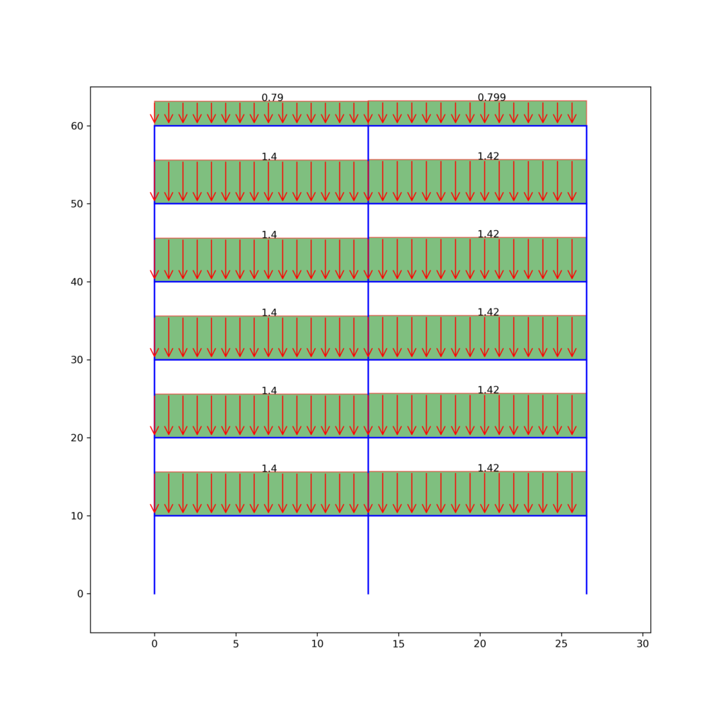
The provided python code can be used for solving building frame under distributed gravity loading as shown in the figure above. Dimensions, load, storey and number of bay can be changed in the script. Note that, force unit is in kilo-pound and length is in feet.
Script
import numpy as np
import matplotlib.patches as patches
import matplotlib.pyplot as plt

height = 10 # Floor height
storey = 6
bay = 2
bay_widths = np.array([13.125, 13.42])
#force_list = np.array([10, 8.5, 7, 5, 3.5, 2])
bay1_roof = 0.79
bay1_other = 1.4
bay2_roof = 0.799
bay2_other = 1.42
force_list = np.ones((storey,bay))
for i in range(storey):
    for j in range(bay):
        if i==storey-1 and j==0:
            force_list[i,j] = bay1_roof
        if i==storey-1 and j==1:
            force_list[i,j] = bay2_roof
        if i<storey-1 and j==0:
            force_list[i,j] = bay1_other
        if i<storey-1 and j==1:
            force_list[i,j] = bay2_other

bay_widths_cm = np.hstack((0,bay_widths.cumsum()))
heights = height*np.ones(storey)
heights_cm = np.hstack((0,heights.cumsum()))

h_line = storey*bay
v_line = (bay+1)*storey

def frame():
    fig= plt.figure(figsize=(10,10))
    ax = fig.add_subplot(1,1,1)

    for i in range(storey):
        for j in range(bay):
            ax.plot([bay_widths_cm[j],bay_widths_cm[j+1]],[heights_cm[i+1], heights_cm[i+1]], color='blue') #Horizontal line

    for i in range(storey):
        for j in range(bay+1):
            ax.plot([bay_widths_cm[j], bay_widths_cm[j]], [heights_cm[i], heights_cm[i+1]], color='blue')
    return fig, ax

fig, ax = frame()
arrow_number=15
for i in range(storey):
    arl = 5
    for j in range(bay):
        ax.text((bay_widths_cm[j]+bay_widths_cm[j+1])/2, heights_cm[i+1]+force_list[i,j]*4 , force_list[i,j])
        for k in range(arrow_number):
                ax.annotate('', xytext=[bay_widths_cm[j]+(bay_widths[j]/arrow_number)*k,
                                        (force_list[i,j]*4)+heights_cm[i+1]],
                xy=[bay_widths_cm[j]+(bay_widths[j]/arrow_number)*k, heights_cm[i+1]],
                arrowprops=dict(arrowstyle="->", color='red'),
                fontsize=12, size=20)
        rect = patches.Rectangle((bay_widths_cm[j],heights_cm[i+1]),
                         bay_widths[j],(force_list[i,j]*4),linewidth=1,
                                 edgecolor='r',facecolor='green', alpha=0.5)
        ax.add_patch(rect)
ax.set_xlim(-bay_widths[0]*0.3, np.max(bay_widths_cm)+bay_widths[0]*0.3)
ax.set_ylim(-height*0.5, (height*storey)+(height*0.5))
fig.savefig('Frame_with_gravity_load.png', dpi=300)

def Moment_line(w=0.79, l=13.125):
    moment = (w*(0.8*l)**2)/8
    #print ('Midspan moment', moment)
    sf_ss_end =(w*(0.8*l))/2
    end_moment= (sf_ss_end*(0.1*l))+ (w*0.1*l*(0.1*l*0.5))
    #print ('Shear:',sf_ss_end)
    #print ('End moment:', end_moment)
    x = np.linspace(-l/2, l/2, 30)
    y = (((-end_moment-moment)/(-l/2)**2)*(x**2))+moment
    return x+l/2, y, moment, end_moment, sf_ss_end, sf_ss_end+(w*0.1*l)

# Bending moment diagram for beams
fig_bm, ax_bm = frame()
end_bm = np.ones((storey, bay))
for i in range(storey):
    for j in range(bay):
        beam_output =Moment_line(w=force_list[i,j], l=bay_widths[j])
        x = beam_output[0]
        y = beam_output[1]
        mid_moment = np.round(beam_output[2], 2)
        end_moment = np.round(beam_output[3], 2)
        end_bm[i,j]=end_moment

        ax_bm.fill_between(bay_widths_cm[j]+x, heights_cm[i+1]+(y*0.2),heights_cm[i+1], color='#78c679')
        ax_bm.text((bay_widths_cm[j]+bay_widths_cm[j+1])/2, heights_cm[i+1] , mid_moment)
        ax_bm.text(bay_widths_cm[j], heights_cm[i+1]-(height*0.35) , end_moment)
        ax_bm.text(bay_widths_cm[j+1]-bay_widths[j]*0.15, heights_cm[i+1]-(height*0.35) , end_moment)

ax_bm.set_xlim(-bay_widths[0]*0.3, np.max(bay_widths_cm)+bay_widths[0]*0.3)
fig_bm.savefig('Moment_diagram_beam_gravity_load.png', dpi=300)

# Shear force diagram for beams
fig_bs, ax_bs = frame()
for i in range(storey):
    for j in range(bay):
        beam_output =Moment_line(w=force_list[i,j], l=bay_widths[j])

        end_shear = np.round(beam_output[4], 2)

        ax_bs.fill_between([bay_widths_cm[j], bay_widths_cm[j], bay_widths_cm[j+1], bay_widths_cm[j+1]],
                           [heights_cm[i+1], heights_cm[i+1]+end_shear*0.5, heights_cm[i+1]-end_shear*0.5, heights_cm[i+1]],
                           heights_cm[i+1],
                           color='#78c679')
        ax_bs.text((bay_widths_cm[j]+bay_widths_cm[j+1])/2, heights_cm[i+1] , end_shear)

        #ax_bm.text(bay_widths_cm[j], heights_cm[i+1]-(height*0.35) , end_moment)
        #ax_bm.text(bay_widths_cm[j+1]-bay_widths[j]*0.15, heights_cm[i+1]-(height*0.35) , end_moment)

ax_bs.set_xlim(-bay_widths[0]*0.3, np.max(bay_widths_cm)+bay_widths[0]*0.3)
fig_bs.savefig('shear_force_diagram_beam_gravity_load.png', dpi=300)

# Bending moment diagram for columns
end_bm
end_cm = np.ones((storey, bay+1))

end_cm[:,0] = end_bm[:,0][::-1].cumsum()
end_cm[:,-1] = end_bm[:,-1][::-1].cumsum()
end_cm[:,1:-1] = np.reshape(np.diff(end_bm)[::-1].cumsum(), np.shape(end_cm[:,1:-1]))

fig_cm, ax_cm = frame()
for i in range(storey):
    for j in range(bay+1):
        moment = np.round(end_cm[::-1][i,j],2)
        ax_cm.text(bay_widths_cm[j], heights_cm[i]+(height/2) , moment)
        scale = .1
        ax_cm.fill_betweenx([heights_cm[i], heights_cm[i], heights_cm[i]+height, heights_cm[i]+height],
            [bay_widths_cm[j], bay_widths_cm[j]+(moment*scale), bay_widths_cm[j]-(moment*scale), bay_widths_cm[j]],

                           bay_widths_cm[j],
                          color='#78c679', interpolate=True)
        #ax_f.add_patch(rect)

#ax_cm.set_xlim(-bay_widths[0]*0.5, np.max(bay_widths_cm)+bay_widths[0]*0.5)
fig_cm.savefig('Moment_diagram_column_gravity_load.png', dpi=300)
Conclusion
Both scripts above will produce shear and bending moment diagram for beam and columns and all the figures will be saved in the directory of script. The script works fine for this setup. Changing dimensions and force will work properly. The script may raise error if bay and storey is changed. Though it should work for any storey or bays of building frame.
Check my other post like this one
https://mohammadimranhasan.com/digitise-geographic-features/
Check my quora profile.

Very good! Up to now I successfully tested the first script, concentrated loads at nodes of each storey which represents earthquakes forces acting on the structure.
Question: have you minded to create a python code for lateral distributed loads, say the well known wind representation?
In such cases also pier supports are charged by forces and the external column (at least).
Thank you for your kind answer
Thanks for your feedback and time for using my script. The wind load was in plan for the next version of the script. But wasn’t able to managed time to write the code. I will try to add the wind load.
Oh yes! I fully agree with you that any search needs time for minding the actions to do and tranferring to code (in python). I may wait for your tentative. Best wishes
Private communication [not to be of public domain]
Reference is made to your second script involving a frame structure with uniform loads on the beams. Some mismatches arise due to my difficulty on understanding the force list applied, i.e., at bay1_roof
and bay1_other.
Could you please, without urgency, get a glance to the structure rallied and zipped in this folder
https://transfer.sh/1WXLsM5/Frame_2bays_3storeys.rar
qiving me (via email, address in written inside) the appropriate python code?
For the sake of simplicity, consider (E,A,J)=constant for all elements. Thx. in advance
Thanks for your suggestions. I will try to look at the issues you are facing with the code.